When using Unity's Shader Graph to create UI masks, procedural stripes, grids, or SDF (Signed Distance Field) shapes, you will almost certainly encounter the problem of "jagged edges (aliasing)".
If you use a Step node to make the borders sharp, they will look blocky and pixelated when the camera gets close. Conversely, if you use a Smoothstep node to blur the edges, they will look nice up close but become overly blurry and faint at a distance, and fine grids might flicker due to moiré patterns.
In this article, we explain the root cause of this rendering artifact and show how to implement a classic Technical Art anti-aliasing technique using DDX (horizontal screen-space derivative) and DDY (vertical screen-space derivative) nodes to keep borders exactly one pixel wide on screen regardless of camera distance or resolution.
1. The Root Cause: Mismatch Between UV Space and Screen Pixels
Why do static Step or Smoothstep nodes fail to render clean borders? The reason is that the screen-space size (in pixels) of one unit of UV space changes dynamically depending on camera distance and resolution.
When you use Step(0.5, UV.x), it outputs exactly 0 or 1. Because the physical pixel boundaries rarely align perfectly with the value 0.5 in UV space, pixels on the boundary cannot have intermediate colors, resulting in a jagged, aliased edge.
What if you fix the transition width to 0.02 using Smoothstep(0.49, 0.51, UV.x)?
- Close-up (Zoomed in): A UV width of
0.02might cover 50 physical pixels on screen. This results in an extremely soft, blurry border. - Far away (Zoomed out): The UV width of
0.02shrinks to less than 0.1 screen pixels. Because the transition happens entirely inside a single pixel, it behaves like aStepnode, causing jagged edges and flickering moiré patterns.
To keep the border sharp but smooth, we need a dynamic transition width that spans exactly 1 to 2 pixels on screen at all times. To do this, the shader needs to calculate how much the target value changes between adjacent screen pixels.
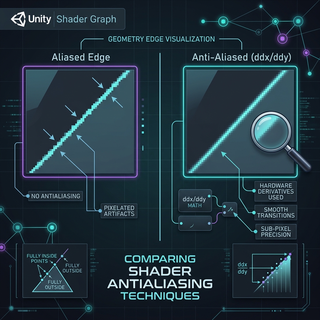
Figure: Visual comparison between a jagged Step node (left) and ddx/ddy screen-space derivative anti-aliasing (right).
2. The Solution: Screen-Space Derivatives (ddx/ddy) and fwidth
When rendering, the GPU does not execute the fragment shader for each pixel in complete isolation. Instead, it runs them in 2x2 pixel blocks called "Quads". This allows the GPU to compute the difference (or slope) of values between neighboring pixels.
We can access this hardware feature using screen-space derivative functions:
DDX(dFdx): Computes the rate of change of a value between the current pixel and its right neighbor.DDY(dFdy): Computes the rate of change of a value between the current pixel and its bottom neighbor.
By adding their absolute values together, we get fwidth(val) = abs(ddx(val)) + abs(ddy(val)), which represents "how much the value changes per screen pixel".
For example, if fwidth(UV.x) is 0.005, it means moving one pixel horizontally or vertically changes the U coordinate by 0.005. We now have a real-time conversion rate from screen pixels to UV space!
3. Implementation in Shader Graph
Using fwidth, we can build an anti-aliased Step function that dynamically adjusts the transition range to cover exactly one pixel on screen.
Step 1: Calculate the Dynamic Transition Width
For a given Threshold, we define the transition range (Edge1 to Edge2) to be exactly 1 pixel wide centered at the threshold:
Edge1 = Threshold - (fwidth(Value) * 0.5)
Edge2 = Threshold + (fwidth(Value) * 0.5)
This maps screen space's 1-pixel width to its equivalent range in UV space. If you want a softer transition (e.g. 2 pixels wide), change the multiplier to 1.0.
Step 2: Interpolate with Smoothstep
Pass the calculated Edge1 and Edge2 into a Smoothstep node along with the original value. This blends the value smoothly between 0 and 1 over exactly one screen pixel, eliminating the jagged edges completely.
💡 Shader Graph Node Setup:
- Prepare the input value (e.g.
UV.xor a calculated procedural gradient). - Connect this value to a DDX node and a DDY node.
- Create Absolute (Abs) nodes for both DDX and DDY outputs, and add them together using an Add node to reconstruct
fwidth. - Multiply this sum by
0.5using a Multiply node. This is the half-pixel offset. - Subtract the half-pixel offset from your target
Threshold(e.g.0.5) to getEdge 1, and add it to the threshold to getEdge 2. - Create a Smoothstep node, and connect
Edge 1,Edge 2, and your original input value to it.
4. Custom Function (HLSL) for Clean Graph Layouts
To keep your Shader Graph clean, you can use a Custom Function node to write this logic in a single line of HLSL code.
Create a Custom Function node, set its type to String, and write the following code:
// Inputs: Threshold (float), Value (float)
// Output: Out (float)
float width = fwidth(Value);
Out = smoothstep(Threshold - width * 0.5, Threshold + width * 0.5, Value);
By saving this as a custom node (e.g. AntialiasedStep), you can easily replace standard Step nodes to clean up jagged edges across your project.
5. Use Case: Procedural Grids and Stripes
This technique is especially powerful when rendering procedural grids and stripes.
Normally, repeating patterns created with Fraction or Sine nodes flicker and show heavy moiré patterns at a distance because the pattern's frequency exceeds the pixel sampling rate.
With anti-aliased thresholding, when the pattern's details shrink below one pixel, the shader automatically averages the output to a neutral gray. This eliminates all moiré artifacts, which is critical for maintaining visual quality in mobile and VR projects.
6. Limitations and Caveats
- Fragment Stage Only: Because screen-space derivatives compare values between adjacent pixels, they cannot be used in the Vertex stage. Using
fwidthorDDX/DDYnodes in the vertex stage will cause compile errors or return 0. - Conflict with Pixel Art Aesthetics: If you are deliberately making a pixelated, retro-style game, this anti-aliasing technique will blur the pixel block boundaries. Make sure to use standard
Stepnodes when hard, blocky edges are desired.
7. Summary: Anti-Aliasing Comparison
| Method | Visuals with Distance | Pros & Cons |
|---|---|---|
| Step Node | Edges are always cut off at pixel boundaries, causing aliasing at all distances. | 🔴 High aliasing and moiré artifacts. Lightweight. |
| Static Smoothstep | Very blurry up close, jagged/pixelated far away. | 🔺 Only useful for static, fixed-distance elements like 2D UI. |
| fwidth (ddx/ddy) | Borders automatically stay exactly 1-2 pixels wide on screen at any distance or resolution. | 💚 Perfect crispness and smoothness. Moiré is automatically resolved. Extremely cheap to compute. |
By replacing standard Step nodes with fwidth-based anti-aliased steps, you can significantly elevate the rendering quality of your procedural materials and custom UI. Stock this HLSL snippet in your project's custom shader library for future use!